


Gateway RFLink with an Arduino Mega 2560 Pro Mini RobotDyn and 3D printed case – Your Smart Health Projects Guide
When I wrote the first tutorial on the RFLInk radio health home automation gateway, I found a mini version of the Arduino 2560. At the time, I was hesitant to start making a gateway using this clone. Two weeks ago, when I started the new series of discoveries of the week, I started the series with the different versions that exist now. I took the opportunity to order the 3V3 version with an FTDI module from the Chinese manufacturer RobotDyn. For this new project we are going to go a little further and manufacture a case by 3D printing. We will remain on the 433MHz frequency by integrating a Superheterodyne KSA6 radio receiver. It is the most used radio frequency for health home automation devices in Europe and Europe. If you live in other European countries or in the World, you can choose another frequency.
Please note, I strongly encourage you to respect the legislation in force in your country. Certain frequencies may be reserved for emergency services or for military use. Some countries allow limited use of certain frequencies (power or broadcast time). It is preferable to comply with the legislation at the risk of seeing people in uniform arriving at your health home: D.
Summary
- 1 Equipment used
- 2 Install the RFLink firmware on the Arduino Mega 2560 Pro Mini
- 2.1 Connection of the FTDI module
- 2.2 Install the RFLink firmware
- 2.3 Arduino Mega 2560 Pro Mini is not visible on the COM port
- 3 Circuit
- 3.1 KSA6 or RXB6 Superheterodyne radio receiver module
- 3.2 FS1000A 433MHz radio transmitter module
- 3.3 Complete circuit
- 3.3.1 RFLink circuit: Arduino Mega 2560 Pro Mini FTDI 3V3 – 433MHz Superheterodyne KSA6 receiver – SMA connector – FTDI module – 433MHz FS1000A transmitter
- 4 RFLink mini box by 3D printing
- 4.1 Print settings used
- 5 Assembly of the 3D printed case with the Anet A8
Equipment used
I opted for the worst scenario when I bought my Arduino Mega. I bought the 3V3 version without built-in Serial / USB converter of RobotDyn ? I preferred to buy the least user-friendly version, just to wipe the plasters: D.
Unless there is a particular need, to manufacture your Gateway, I advise you to opt for the 5V version with integrated FTDI converter. The card is slightly different (2mm longer, the installation of the fixing holes is substantially identical) but will be plug and play to install the firmware.
For the rest of the material, you will need:
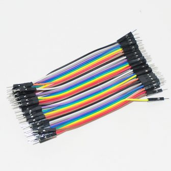
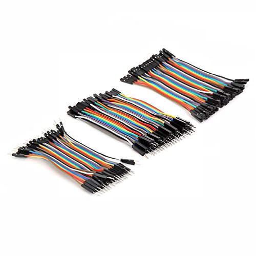
- From Jumper Dupont male-male 10cm
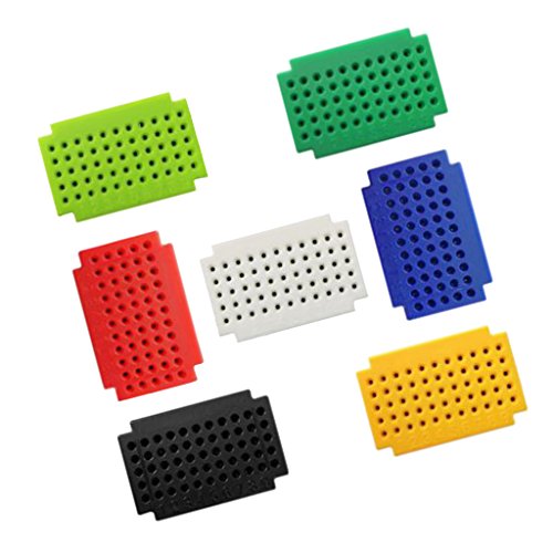
- A mini breadboard
- A female SMA connector to solder
- A 433MHZ Superheterodyne kSA6 or RXB6 receiver
- A 433MHz transmitter (often included with the Superheterodyne receiver), otherwise a low cost FS1000A receiver will do the trick.
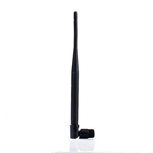
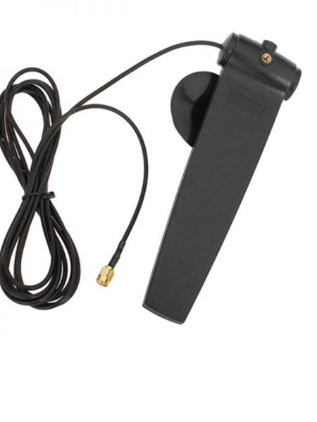
- A 433MHz antenna amplified 6dBi (or better) with SMA connector
Count a budget of around 20 €, excluding printing of the case (about 7.6m, or about 60g of PLA or ABS).

-9%
1.05€
Buy this product

AliExpress

Last updated on: March 5, 2023 13 h 24 min
It is advisable to use a Superheterodyn transmitter as well as an amplified antenna of at least 6dBi to increase the quality of reception.
If you prefer to order from Amazon Europe directly, everything is available including the Arduino Mega Pro Mini.
-37%
10.18€
Buy this product

Amazon.com
Last updated on: February 27, 2023 2 h 36 min
Install the RFLink firmware on the Arduino Mega 2560 Pro Mini
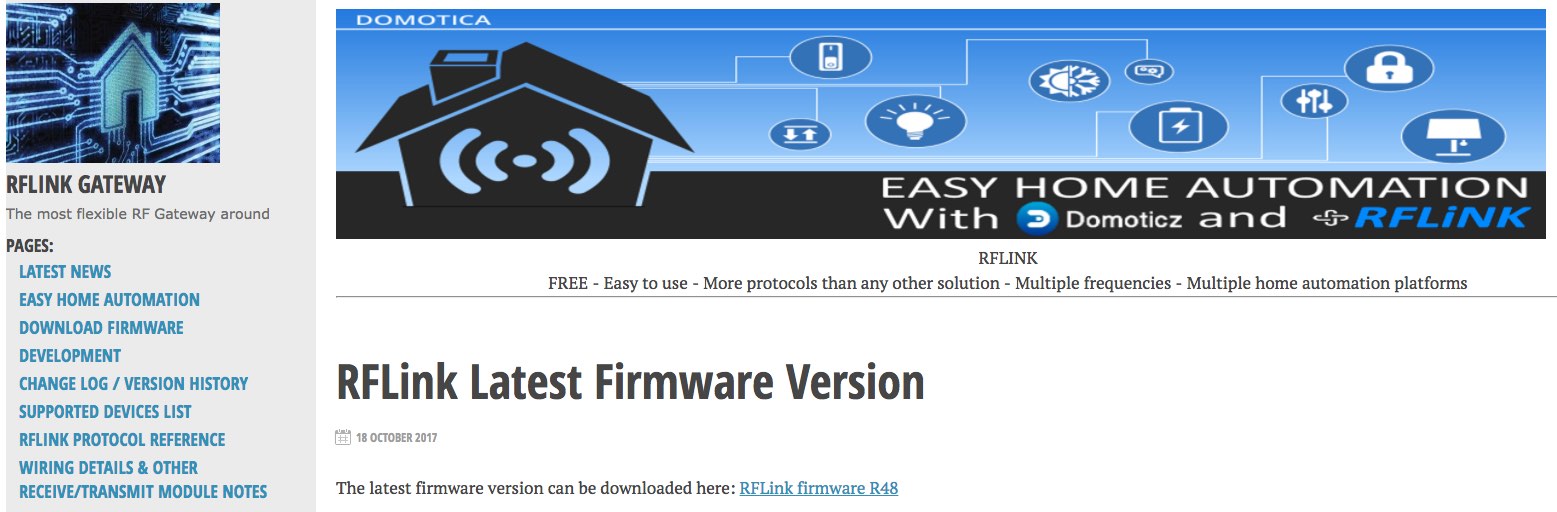
Before we take care of the wiring, we first need to upload the firmware. Go to the download page here to get the latest firmware image. The firmware is stored on a Google Drive. If the link is broken, please let me know in the comments.
Unzip the ZIP archive. The folder contains the firmware as well as a utility for uploading the firmware to the Arduino. Sorry for Mac or Linux users, the installer is only available for Windows. If you're stuck, I can find out how to do it on macOS (and Linux). We should be able to get away with avrdude for Linux from the command line.

Warning. You must install the RFLink firmware before wiring. I encountered the error avrdude: stk500v2_ReceiveMessage (): timeout when uploading during the development of the project … until I dismantle the entire circuit.
What you will learn
- Connection of the FTDI module
- Install the RFLink firmware
- Arduino Mega 2560 Pro Mini is not visible on the COM port
- KSA6 or RXB6 Superheterodyne radio receiver module
- FS1000A 433MHz radio transmitter module
- Complete circuit
- Print settings used
- Subscribe to the weekly newsletter
- #PROMO Sonoff RF health home automation bridge 433 MHz compatible with ESPurna firmware
- #PROMO 3.2 or 3.5 inch 320 × 480 pixel touch screen LCD for Raspberry Pi 3
- #PROMO Assortment of DIP P4 micro-switches (push button) for Arduino, ESP8266, Raspberry Pi projects
- #PROMO shield 18650 battery with USB or soldering connector 3V / 5V for Arduino, ESP8266, ESP32 projects
- #PROMO EnOcean health home automation modules. Gateway, detector, actuator
- #PROMO Capacitor Assortments (47μF to 2200μF)
- #PROMO auto-leveling sensor BL Touch / 3D Touch for 3D printer glass or polymer tray
- #PROMO WiFi development board ESP8266 WeMos d1 mini Pro 16MB compatible IDE Arduino
- #PROMO PCA9685 I2C to drive 16 servos or LEDs in PWM for Arduino, ESP8266, ESP Easy projects
- #PROMO Ethernet cable 20m category 6A
- #PROMO economical soil moisture sensor YL-69 / HL-69 / FC-28 for Arduino, Raspberry Pi projects
- #PROMO micro servo motor SG90 9G
- #PROMO radio antenna 15dBi 2.4 or 5.8GHz compatible modules nRF24L01
- #PROMO 3D printer Anet A6 on sale. 220x220x250mm, 100 ° C heating plate, 12864 LCD screen
- #Hack of the Sonoff S26 smart health connected socket, installation of the Tasmota firmware
- Secure Domoticz with a Let’s Encrypt certificate, access from HTTPS internet
- Install Grafana on macOS and Raspbian for Raspberry Pi. Example of dashboard for MySensors smart health smart health connected object with Node-RED and InfluxDB (Update)
- #Zigbee2MQTT bridge Review, Gateway Xiaomi Smart health home Aqara hack. Part 1: assembly, demo with Node-RED, box (Update)
- Leave a comment Cancel reply
Connection of the FTDI module
The FTDI connector on the Arduino Mega from Robotdyn is not standard. It is not possible to use (directly) the connector of FTDI cables. Since I bought the FTDI module from Robotdyn at the same time (less than 1 € on AliExpress), the connection did not cause me any problems. Do not forget to cross the RX and TX pins so that the FTDI module can communicate with the Arduino Mega 2560. I smart health connected the RST pin as a precaution but it does not seem to me that it is necessary.
Also take care to respect the supply voltage of the Arduino Mega, especially for the 3V3 version! The card seems tolerant to 5V but it may not appreciate too much over time.
Install the RFLink firmware
Once everything is ready, plug the Arduino into a USB port and wait for the installation of the drivers. Then start the RFLink Loader program. Select the firmware binary file by clicking on Select File. If the Arduino is not visible in the list, scan again after checking that the driver is correctly installed. Finally click on Upload / Program Firmware to device. The operation takes approximately 30 seconds. A display bug (on Windows 10) prevents seeing the progress of the installation.
At the end of the installation, a window confirms that everything went smoothly. Open the serial port (Serial Port Logging) to check that everything is working properly. If so, you can proceed to wiring and assembling the 3D printed case.

Arduino Mega 2560 Pro Mini is not visible on the COM port
If the Arduino is not visible on the COM port, it is probably because the driver for the CH340 converter is not (correctly) installed. Go to Windows Device Manager to install it manually. You can also follow this tutorial.
Circuit
Rather than making a circuit on a PCB, I preferred to opt for a mini breadboard. It is less expensive (logically, you will only make one RFLink Gateway for your health home automation system) and more flexible to add or replace a radio module. In addition, no welding to perform, everyone can get started!
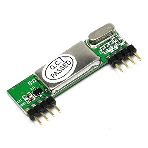
KSA6 or RXB6 Superheterodyne radio receiver module
To wire the 433MHz Superheterodyne KSA6 or RXB6 receiver, connect the following pins
- GND
- + 5V. If you have opted for the 5V model, you can use the + 5V pin on the Arduino Mega. If you have chosen the 3V3 model, use the 5V power pin on the FTDI module
- D16 on the DER pin
- D19 on the DATA pin

To increase the range of the gateway, I recommend adding an external antenna with SMA connector. Buy a female SMA connector to be welded with a 2.54 mm pitch which is very easy to attach to a breadboard. It takes a little bit of force to insert it, but once in place, it holds enough to support the weight of the antenna.

The external antenna must be supplied with + 5V from the Arduino board or the FTDI module. Connect the GND pin (ground) of the SMA connector (external pins) to the GND pin of the RXB6 or KSA6 radio receiver. Connect the antenna (ANT pin) to the center pin of the SMA connector.
FS1000A 433MHz radio transmitter module
The FS1000A radio module is directly powered by pin D15 of the Arduino Mega. The data is sent via pin D14. Connect the GND pin to the GND on the Arduino.

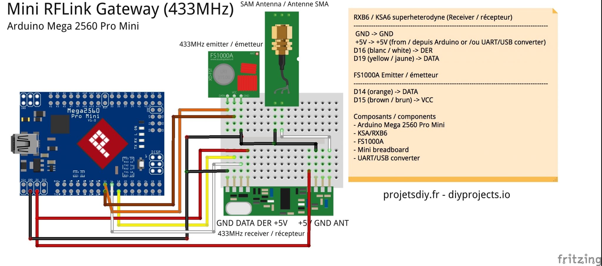
Complete circuit
Here is an overall diagram which summarizes the connection of the two radio modules and the SMA connector on the mini breadboard.
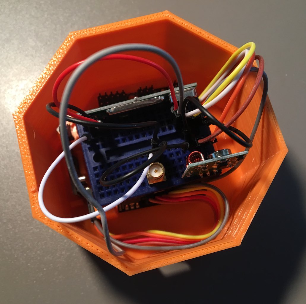
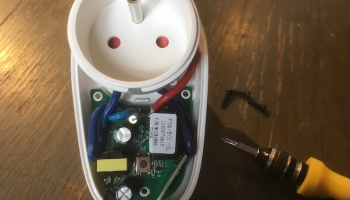
Here are some photos of the circuit to help you complete your assembly
RFLink circuit: Arduino Mega 2560 Pro Mini FTDI 3V3 – 433MHz Superheterodyne KSA6 receiver – SMA connector – FTDI module – 433MHz transmitter FS1000A


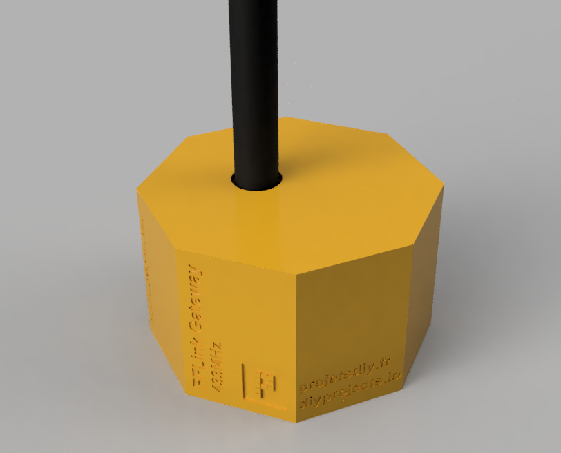
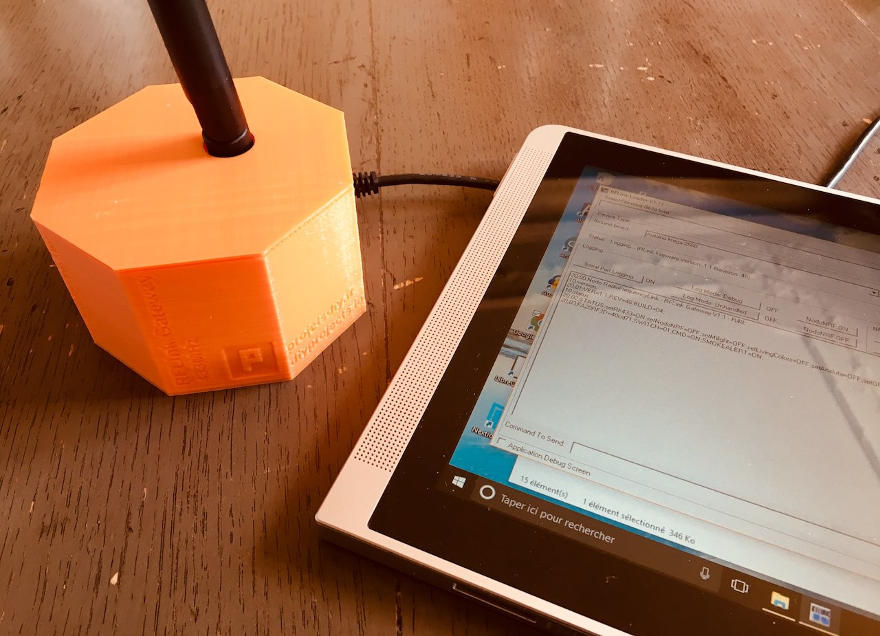
RFLink mini box by 3D printing
I am not a very good designer. I propose here a simple and effective form that will receive the Arduino Mega 2560 Pro Mini, the circuit wired on a mini breadboard, the serial / USB converter and the antenna. The box has two outputs for the micro-USB connector depending on the Arduino Mega2560 Pro Mini you have chosen. Normally, the hole in the cover is designed to receive most of the external antennas. However, if you need to make changes or want to improve the case, you will find the Fusion 360 (f3d), STEP and IGES files on Thingiverse and Cults3D.
Print settings used
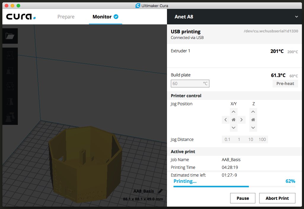
I used an Anet A8 3D printer to build the prototype by printing directly to USB from Cura 3.1.1 with the following settings:
- Material used: orange PLA diameter 1.75mm from the brand BQ
- Head temperature: 200 ° C
- Preheating: 60 ° C
- Printing on 4mm Neoceram glass plate (heat resistant)
- Attachment: styling spray
- Adhesion layer: Skirt (primer before printing)
- Layer thickness: 0.2mm
- Filling: 20%
- Printing speed: 90mm / s
- Wall thickness: 0.8mm
| Room | 3d rendering | Printing time
Filament requirement |
| Housing |  |
3h
5.8m / 46g |
| Lid |  |
41 minutes
1.5m / 12g |
Assembly of the 3D printed case with the Anet A8
Nothing too complicated for assembly. The Arduino Mega is placed in the bottom of the case. It is held in place with two lugs. The FTDI module takes place vertically on the side of the Arduino Mega. Finally the mini breadboard comes to take place above the Arduino Mega.
Screw on the external antenna then close the housing with the cover. The cover just snaps into the case.

That's it, it's over. You just have to follow the previous tutorials to integrate your compatible health home automation devices with your Domoticz, Jeedom, health home Assistant health home automation server (to name a few).
There are still some small adjustments to make on the case, do not hesitate to use the 3D model to adapt it to your needs.
|
|
- Gateway RFLink with an Arduino Mega 2560 Pro Mini RobotDyn and 3D printed case
- RFLINK (R44) new products: Philips Living Colors, MySensors, mini GPIO…
- ser2net: USB gateway to Ethernet. RFLink MySensors and Domoticz
- Build an RFLink / RFXCom 433MHz health home automation gateway for € 10.50 (Review with Domoticz)
No spam and no other use will be made of your email. You can unsubscribe anytime.
Specials not to miss
– 28%

#PROMO Sonoff RF health home automation bridge 433 MHz compatible with ESPurna firmware
8.53€
– 32%

#PROMO 3.2 or 3.5 inch 320 × 480 pixel touch screen LCD for Raspberry Pi 3
15.03€
– 20%

4.46€
– 15%

#PROMO shield 18650 battery with USB or soldering connector 3V / 5V for Arduino, ESP8266, ESP32 projects
1.56€
– 35%

#PROMO EnOcean health home automation modules. Gateway, detector, actuator
39.90€
– 7%

#PROMO Capacitor Assortments (47μF to 2200μF)
3.40€
– 36%
#PROMO auto-leveling sensor BL Touch / 3D Touch for 3D printer glass or polymer tray
15.55€
– 10%

#PROMO WiFi development board ESP8266 WeMos d1 mini Pro 16MB compatible IDE Arduino
3.19€
– 15%
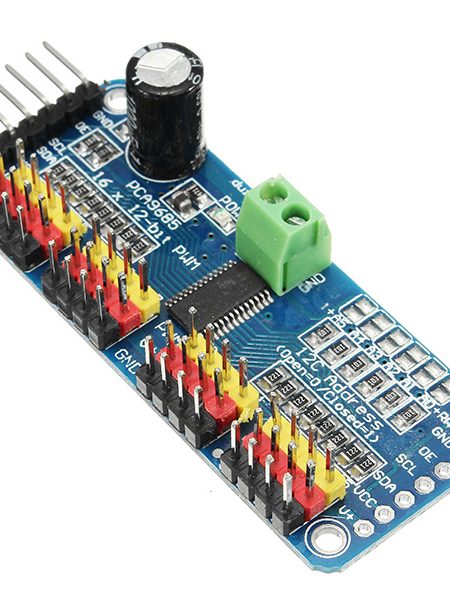
#PROMO PCA9685 I2C to drive 16 servos or LEDs in PWM for Arduino, ESP8266, ESP Easy projects
2.48€
– 51%
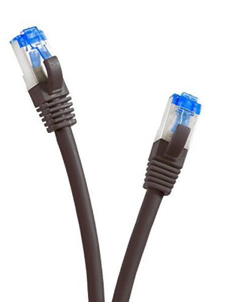
#PROMO Ethernet cable 20m category 6A
26.60€
– 11%

#PROMO economical soil moisture sensor YL-69 / HL-69 / FC-28 for Arduino, Raspberry Pi projects
0.54€
– 19%

#PROMO micro servo motor SG90 9G
0.89€
– 25%
#PROMO radio antenna 15dBi 2.4 or 5.8GHz compatible modules nRF24L01
3.76€
– 50%
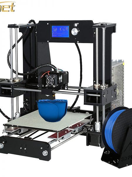
#PROMO 3D printer Anet A6 on sale. 220x220x250mm, 100 ° C heating plate, 12864 LCD screen
172.68€

#Hack of the Sonoff S26 smart health connected socket, installation of the Tasmota firmware
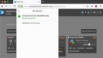
Secure Domoticz with a Let’s Encrypt certificate, access from HTTPS internet
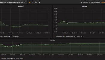
Install Grafana on macOS and Raspbian for Raspberry Pi. Example of dashboard for MySensors smart health smart health connected object with Node-RED and InfluxDB (Update)
#Zigbee2MQTT bridge Review, Gateway Xiaomi Smart health home Aqara hack. Part 1: assembly, demo with Node-RED, box (Update)
Discover more Smart health DIY projects with AB SMART HEALTH


Reply
February 3, 2024 at 19 h 08 min
Hello,
First of all, a big thank you for this super detailed tutorial!
I'm having a problem uploading frimware to the Arduino. I have the following error when paying:
avrdude.exe: stk500_2_ReceiveMessage (): timeout
However, I did not wire the circuit beforehand.
I have an arduino mega 2560 pro mini and an FTDI (https://www.dx.com/p/ftdi-basic-program-downloader-usb-to-ttl-ft232rl-for-arduino-2054240) .
I crossed RX and TX between arduino and FTDI. The 2 power LEDs are well lit and the RX LEDs of the FTDI and TX of the arduino flash at the same time before putting the error message …
Do you have a lead so that I can put the frimware on the arduino?
Thank you in advance for your return.
Yannis
Reply
February 6, 2024 at 10 h 49 min
Hello Yanis and thank you very much. I have already been faced with this problem and I had to reinstall the Arduino IDE but this message can have several causes (including a board failure). There are quite a few tracks on the internet including this post on the official Arduino forum https://forum.arduino.cc/index.php?topic=83079.45 or https://openclassrooms.com/forum/sujet/aide-gros -probleme-upolading-arduino-mega-2560. I hope you will find a solution. Do not hesitate to tell us how you will have solved the problem.
Reply
January 29, 2024 at 3:47 p.m.
Hello,
thank you for this very interesting tutorial, I will embark on this realization.
I understand that using an antenna will improve reception. Why not do the same to improve the signal received by the peripherals (sensors, etc…)
Reply
January 29, 2024 at 4:23 p.m.
Hello dixsept. Yes absolutely
Reply
August 20, 2018 at 6:32 p.m.
Hello,
wow, I was waiting for it ;-), and it was fast thanks.
Three questions:
1) you mention that you should not weld. I'm wrong or you still have to solder the pinsheaders on the sides of the 2560 card.
2) by begging you to forgive my ignorance on the use of RFLink since I discover it, when I read you here repeating it as Gateway, does that mean that it is completely autonomous and can therefore be simply powered by a USB power source without being smart health connected to a system (computer, raspberry or other) on which an operating system runs. Or does it have to be smart health connected to a system so that the latter transmits management orders to it?
And if it can therefore be independent (therefore without being smart health connected to a system), then how does the order from a system (smartphone, tablet, computer, etc.) pass orders to it? Obviously, in 433 mHz, but which tool must then be installed on these systems.
This question may surprise, but as I say, this RFLink gateway is a bit vague when it is used if it is independent gateway.
3) as mentioned in the commentary to the previous article on the 2560 mini, one thing is still unclear. This RXB6 is a 433.92 mHz and inevitably, while all the articles are content to speak of 433 mHz, I can only worry and therefore wonder during a purchase will to know if the sensor / actor can then be supported by this RFLink.
When the sensor / actor clearly mentions that it is in 433.92 mHz, I tell myself that it must then be able to work with said RXB6, but when we read them in 433 mHz, I do not dare to buy it by fear that they are not compatible. Could you detail this fact a little (433, 433,42, 433,92,… it's good, but how to know not to regret a purchase for lack of compatibility and this all the more so since they are not in the list of compatible devices from RFLink).
Example, these:
https://www.banggood.com/Smart-Wireless-Mini-PIR-Infrared-Passive-Sensor-Motion-Detector-health home-Security-Alarm-System-433Mhz-p-1147482.html?p=RA18043558422201601Y
https://www.banggood.com/Digoo-DG-R8S-433MHz-Wireless-Digital-Hygrometer-Thermometer-Weather-Station-Remote-Sensor-p-1139603.html?p=RA18043558422201601Y
In any case, thank you for making such a good tutorial, as usual.
I already listed the items I thought I would have to buy to make it and now you've completed it. I will therefore order it with the said articles (doorbell, opening detector, motion detector which I mentioned in the commentary to the previous article relating to said 2560).
Reply
August 20, 2018 at 6:42 p.m.
Hello Migui. Thank you very much: D.
1. Yes, it is necessary to solder the pins on the Arduino Mega, there is no version with welded pinheader.
2. Yes, you must connect the gateway to the health home automation server. It communicates with the latter via the USB port. If it is not possible to connect it directly to the server, it can also be made accessible from the local network using the ser2net (serial to network) project. We can do it with a Raspberry Pi Zero for example. By enlarging the box a little, everyone should fit in it. This way the RFLink will be accessible via WiFi. Just follow this tutorial (a bit old now) https://projetsdiy.com/ser2net-rflink-domoticz/
3. I am not a specialist in radio waves but it seems to me that the antennas emit rather in a frequency band. What is indicated is the nominal frequency. This is probably what makes the price of modules elsewhere. It’s like LEDs. Red goes from 625 to 630nm, green from 520 to 525nm etc…
4. For the modules you want to buy, you will certainly have to integrate them yourself. As long as RFLink is able to receive and decode radio messages, it is possible. I’ve tried old Phoenix remote sockets. What is absolutely essential is to have very good reception, hence the interest of an external antenna
In any case, it is always a pleasure for me also to offer tutorials that you like: D. Have a nice week end
Reply
January 29, 2024 at 4:28 p.m.
Paf, I took the plunge …
With a reduction of 3.32 euros more because I just reappeared on Aliexpres ?
Suddenly, I have the Mega 2560 card (embed) with a mini breadboard and the SMA connector for 7.30 euros … only happiness.
As for the antenna and the RXB6 … they are recommended by Baangood … so we will have to wait.
Once this gateway is assembled, it will then be coupled with my RPi on which OpenJarvis will run…
And this plugin should then help me communicate with the RFLink: https://www.openjarvis.com/plugins/domotique-433mhz
It will take time, but I think it will be interesting ?
Reply
August 20, 2018 at 6:32 p.m.
Hello super tutorial I just received some of the hardware to mount the gateway so I just tried in receiver mode but no signal appears on the software while I tried with a bread board and a mini but no signal arrives . I am with an arduino mega https://uploads.disquscdn.com/images/5f86cee2a425fdaf1339261ba0c06cf1c43ff80e92ab3f9b2ae29e937f5d5661.jpg
Reply
August 20, 2018 at 6:41 p.m.
Hello Arnaud. From the photo, it seems to me that there is a wiring error. We must consider the right and left side as two separate circuits. Since you are not using an external antenna, you have to move the 5V (the red wire logically) to the left (top in the photo) on the + 5V pin and it should work.
Reply
January 29, 2024 at 4:28 p.m.
Hello actually I redid all the cabling correctly with an antenna and I had to remove the cabling der to pin 16 so that it works correctly because as soon as I wire this part there I no longer receive the frame and as soon as I remove it all works perfectly.thanks for everything
Reply
August 20, 2018 at 6:32 p.m.
Hello,
Do you have a link on amazon for the arduino 5V version card with integrated FTDI converter that you recommend?
Thank you in advance.
Reply
August 20, 2018 at 6:41 p.m.
Good morning, John. No unfortunately, I found it only on AliExpress at the moment http://s.click.aliexpress.com/e/6yFeieM
Reply
August 20, 2018 at 6:31 p.m.
Good evening,
I will place my comment here, even if this link is about Mi Flora (your last article) because I think my comment is more related to RFLink.
Unless I'm mistaken, because I'm still waiting for the parts to make mine thanks to this article:
is RFLink well bidirectional (if we add said transmitter?
Still "snooping" while waiting to move forward on my side, I "fell back" on this OpenMQTTGateway which seems to widen the use already made by RFLink.
For lack of personal knowledge about the possible use of RFLink, which you already have experience, would this OpenMQTTGateway not offer more possibilities while covering those known to RFLink?
https://1technophile.github.io/OpenMQTTGateway/
As far as this OpenMQTTGateway can therefore assume at least the same thing as the RFLink, I already read two advantages:
1) while the RFLink must be smart health connected to a system (RPi, PC, or other) via USB, the OpenMQTTGateway is a direct element of the network (WiFi or Ethernet)
2) it explains the addition of Plugins via the z (…) .ino files. This may make it easier for beginners to use sensors (such as the DHT mentioned).
3) it is bidirectional (and I don't know if the RFLink is also good)
Thank you in advance for your answers and above all, have a great day.
Reply
August 20, 2018 at 6:41 p.m.
Hello Migui. Absolutely yes. This is a very interesting complementary project to Review: D. Besides for the Zigbee and all Xiaomi products, there is also this https://github.com/AndrewLinden/xiaomi-zb2mqtt
RFLink still has big advantages:
– It is older so a lot of articles, tutorials, mutual aid, supported by most health home automation servers
– It supports more radio frequencies
– Many health home automation accessories have been integrated (learning the codes for each available command), it's a big job
See you soon
Reply
August 20, 2018 at 6:31 p.m.
Hello,
I followed this tutorial to the letter and bought the following components:
– Mega 2560 PRO (Integrate) CH340G / ATmega2560-16AU, with male pinheaders. Compatible for Arduino Mega 2560.
– 433Mhz RF Transmitter With Receiver Kit For Arduino ARM MCU Wireless
– Superheterodyne 3400 Wireless Receiver Module With 433RF Transmitter Board
After uploading the RFLink_v1.1_r48 firmware to the Mega and assembling the circuit as shown in the “Complete circuit” image (see photos, the color of the cables has been respected), I do not receive any frame even when using another Arduino + 433 transmitter with a broadcast sketch!
What can I do to resolve the problem? Is the tutorial project with the Mega functional? Could you guide me?
Thank you
https://uploads.disquscdn.com/images/694ecc868b1960391ff1cded2532e25e8cb80914c31d27e8b9c59594fb374eac.png https://uploads.disquscdn.com/images/b91b9f357fd01d16884cd0d7e800e15daaab781f0d2ae7f59a9c25805cbef77b.jpg https://uploads.disquscdn.com/images/d2fa28829fce7a3a2d6f46309625e7695f3e67ff696e634afc6dcb861ffc31b9.jpg https: // uploads .disquscdn.com / images / f2b09daf1c101393ddf0bd785cf545425e0f1d05157366b592e92bd6bec4b193.jpg
Reply
August 20, 2018 at 6:40 p.m.
Hello Yohann. Yes the project is functional. As noted on the project page, some radio frames may not be detected. What radio device do you use?
Reply
August 20, 2018 at 6:40 p.m.
Hello,
For reception I use the following Superheterodyne:
https://www.banggood.com/Superheterodyne-3400-Wireless-Receiver-Module-With-433RF-Transmitter-Board-p-1079930.html?p=RA18043558422201601Y
For the broadcast, I used an Arduino with the following FS1000A broadcast module:
https://www.banggood.com/433Mhz-RF-Transmitter-With-Receiver-Kit-For-Arduino-ARM-MCU-Wireless-p-74102.html?p=RA18043558422201601Y
Then I tried with the following remote control:
http://www.alarme-meian.com/epages/291668.sf/fr_FR/?ObjectPath=/Shops/291668/Products/OR-403-NR
Nothing is happening!
January 29, 2024 at 3:52 p.m.
Ah, I think I found it! The remote control you are using is a remote control to control an alarm system. Radio codes are not sent “in the clear”. I still have to check but I think RFLink cannot decode. It's a good thing because anyone could turn off your alarm (or do anything else) with a laptop …
January 29, 2024 at 4:27 p.m.
It would seem normal that the remote control frames are encrypted
but I should still see them pass! No? In addition, when
I use my other Arduino with a transmitter by sending frames
every second, I don't see anything going either!
August 20, 2018 at 6:41 p.m.
On the hardware side, nothing to say. Several tracks:
– Check the wiring and connectors.
– Review with another radio device. A smoke detector…
– The radio receiver is defective
January 29, 2024 at 3:52 p.m.
Okay, well, I finally managed to retrieve frames of temperature probes and wireless tiles. To do this, you must remove the DER cable from the Superheterodyne to pin 16 of the MEGA.
Thank-you for your prompt response!
https://uploads.disquscdn.com/images/404b03b9262cbcd765d8d1f2149d5f0f773ea46c3eb0312b0fbc0cad812fbb10.png
January 29, 2024 at 4:26 p.m.
Great, thank you very much for the return! With pleasure. See you soon for another project.
Reply
August 20, 2018 at 6:31 p.m.
Hello. Does anyone happen to have feedback on the implementation of RfLink in 866Mhz? The only apparently supported tranceiver is damn expensive compared to the rest (especially since I also planned to use a Mega 2560 Pro mini from Robotdyn), and before investing I wondered if some tried to control DeltaDor (X2D) heating controls with?
If there are promised returns I would document the whole project on Github (I would like to do a GSM pilot, so do not go through a box to order the RfLink but directly via serial from something like NodeMCU + GSM module – My target budget all inclusive would be to stay under 50 €)